The Invisible Gap Between Creative Concepts and Physical Products
Great ideas often die at the factory door because they lack a clear path from the drawing board to the assembly line. Navigating the journey from an initial concept to a finished box on a shelf is the ultimate test for any hardware company. Success requires a bridge between creative design and technical execution. Building this bridge early ensures that products are not only beautiful but also practical to build and scale.
Why Product Development Needs More Than a Single Service
Moving toward an integrated approach is the only way to ensure quality and speed in a competitive market. Treat design and manufacturing as one system rather than separate, isolated steps.
The Risks of a Fragmented Supply Chain
Relying on one company for design and another for manufacturing is like trying to build a house with a blueprint and a contractor who speak different languages. Each party works within their own bubble. The designer focuses on how the product looks and feels in a digital space. The manufacturer focuses on how quickly and cheaply they can run the machines. When these two goals do not meet, the project suffers from missed deadlines and high scrap rates.
Fragmented services often lead to a "throw it over the wall" mentality. The design team finishes their work and hands it off without understanding the limitations of the factory floor. This results in products that are difficult to mold or impossible to assemble by hand. These mistakes do not appear until thousands of dollars have been spent on tools. This gap is the primary reason why many hardware startups fail to scale their initial prototypes into mass-produced goods.
Moving Beyond Commodity Molding
Many organizations treat injection molding as a commodity. They select suppliers based mostly on the lowest piece price. In this setup, the supplier's only job is to follow the drawing exactly. There is little incentive for them to suggest part consolidation or better assembly features. This often results in a design that is technically "correct" but commercially inefficient.
Framing the work as an integrated manufacturing solution changes the relationship. In this model, the partner participates in early reviews and helps develop the process on machines similar to those used in final production. This allows both sides to collaborate on choices that improve manufacturability. By viewing the supplier as a technical partner, companies can unlock hidden savings that a simple quote for parts would never reveal.

Building a Smoother Path From Design to Production
Creating a cohesive workflow ensures that every technical decision supports the final goal of efficient mass production. This unified approach removes the friction that usually slows down a hardware launch.
Bridging the Design and Engineering Divide
Designers focus on user experience and aesthetics, while engineers focus on physics and mechanics. While both are necessary, they often conflict. A designer might want a seamless case for a device, but an engineer knows that such a design might warp during the molding process. To build a smooth path, these two departments must work in parallel rather than in a sequence.
This work style is often referred to as concurrent engineering principles, which suggest that product design and manufacturing process planning should happen at the same time. By involving production experts during the earliest sketches, companies can ensure that every aesthetic choice is also a practical one. This alignment prevents the need for major redesigns later in the schedule, which are the primary cause of missed launch dates and budget overruns.
Managing the Technical Handover
The moment a design becomes a manufacturing instruction is a critical pivot point. This handover involves translating CAD models into tooling designs and assembly instructions. If the design team understands the production process, this transition is almost invisible. They provide files that already account for material shrinkage, wall thickness, and draft angles.
When this handover is messy, the production team has to spend weeks "fixing" the design to make it manufacturable. This is a waste of time and resources. A streamlined path from Design to Production eliminates this middle step, allowing the project to move directly from validation to the start of the manufacturing run. This efficiency is the hallmark of a mature product lifecycle management process where geometry, materials, and tolerances are controlled in one shared environment.
Aligning Product Design With Engineering and Manufacturing Requirements
True efficiency comes from designing a product with its own creation in mind. This technical alignment ensures that every part is optimized for the specific machines that will build it.
Applying Practical Design for Manufacturing Guidelines
Design for Manufacturing (DFM) is the practice of designing parts so they are easy and affordable to produce. This involves looking at the geometry of a part and asking if it fits the capabilities of the chosen manufacturing method. For example, if a part is being made through injection molding, it needs specific features like uniform wall thickness to prevent sink marks or warping.
Aligning design with manufacturing also means choosing the right processes for the right volume. By integrating these requirements into the design stage, companies avoid the "unbuildable" designs that haunt many hardware projects. To keep these requirements in view, engineers should follow a standard set of practical checks during the early design phases.
| Design Area | Practical Guideline |
|---|---|
| Wall Thickness | Use uniform walls: core out heavy sections to reduce sink, warp, and cooling time. |
| Draft Angles | Add sufficient draft on all molded faces, especially textured surfaces, for easy ejection. |
| Ribs and Bosses | Use ribs for stiffness: support bosses and keep boss walls thinner than main walls. |
| Radii | Replace sharp internal corners with radii: smooth out thickness transitions to reduce stress. |
| Gates and Vents | Gate into thicker areas: keep cosmetic faces away from gates: vent flow ends properly. |
| Assembly | Add pins, tabs, and snap fits: keep fastening areas flat and accessible for tools. |
Material Selection and Structural Integrity

The choice of material affects more than just the cost: it dictates how a part will behave during production and how long it will last in the hands of the consumer. Different plastics and metals have different flow rates, cooling times, and strengths. An integrated team can suggest a material that meets the strength requirements while also being easy to mold, which keeps cycle times low.
Structural integrity is also a major factor. If a part is designed poorly, it might fail during the assembly process or under the stress of daily use. Engineers can run simulations to see where a part is likely to break. Following established DFM guidelines for technical parts is essential for ensuring that the final product can withstand real-world conditions. Poor flatness on a sealing surface or a mounting area that is too thin can lead to leaks or cracks that appear only after the product is in use.
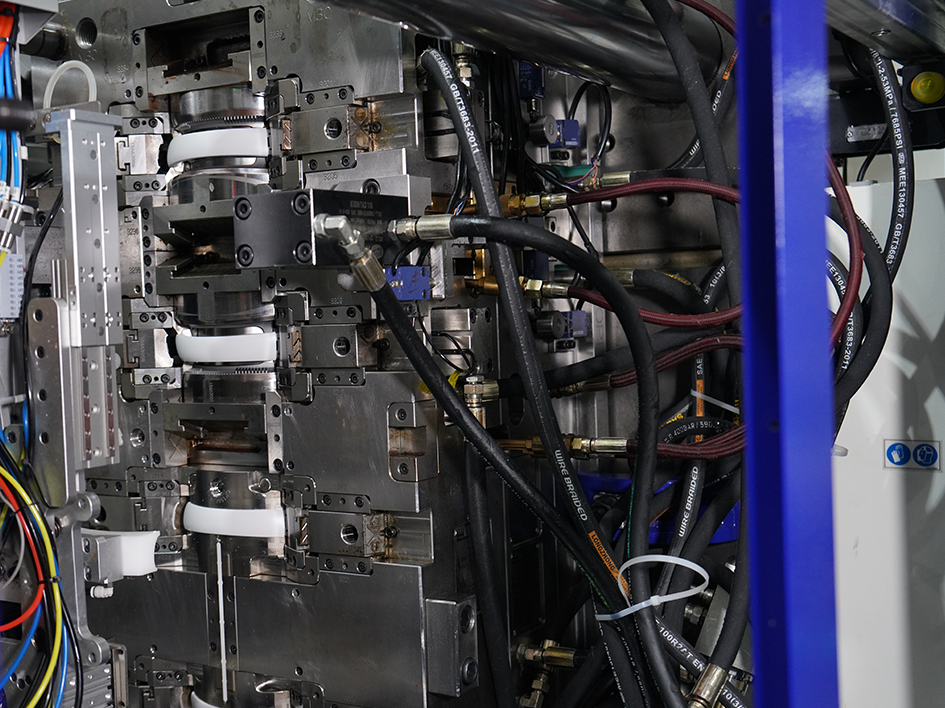
Connecting Tooling, Molding, and Assembly Early in Development
Tooling is often the most expensive and time-consuming part of bringing a new product to life. Connecting this phase with assembly planning ensures the hardware is ready for production.
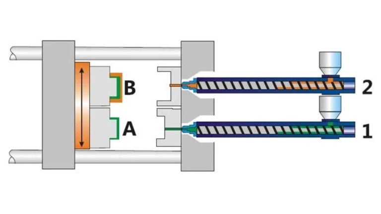
Optimizing Tooling for High Volume

The mold is the heart of the production line. A poorly designed tool will produce parts with defects like flash, warping, or short shots. By involving tooling experts early, the design can be tweaked to allow for better cooling channels and simpler ejection systems. This leads to a tool that lasts longer and produces parts more consistently.
When tooling is considered early, the team can also plan for multi-cavity molds. This allows the factory to produce several parts in a single cycle, which drastically reduces the cost per unit. These decisions must happen during the design phase because the geometry of the part determines how the tool must be built. Successful mold design requires a deep understanding of how molten plastic moves through a steel cavity under high pressure.
Integrating Molding With Assembly Needs
A part might look perfect when it comes out of the mold, but if it is difficult to snap onto another part, the assembly line will slow down. Connecting molding and assembly early means designing parts with "self-aligning" features. These are small tabs or slots that guide the parts into place during assembly.
This level of integration also helps with quality control. If a molded part is designed to only fit one way, it is impossible for an assembly worker to put it together backward. This concept, known as error-proofing, ensures that every unit coming off the line is identical and functional. Building these features into the tool ensures that quality is part of the physical component, not just a result of worker skill.
How Cross-Functional Capabilities Help Reduce Later Changes

Changes made at the end of a project are incredibly expensive. Using a cross-functional approach allows teams to identify and fix problems while they are still just lines on a screen.
Managing Engineering Debt in Hardware
In hardware design, engineering debt refers to those tasks related to engineering design and validation that were delayed due to time constraints. This might include a lack of a DFM review, a design freeze before simulations are concluded, or a decrease in the number of prototype iterations.
Every one of these decisions may look like a viable solution to a problem at hand, yet they will pose issues that will need addressing at a later point in time. Considering engineering debt as a real liability helps keep these things in perspective. Although some debt can be allowed if time is of the essence, it should always be known about and "paid off" before becoming an issue during production and assembly. If ignored, this debt results in expensive tool changes and scrap after the product has already launched.
Avoiding Expensive Engineering Change Orders
An Engineering Change Order (ECO) is a document used to track changes to a product after the design has been finalized. Each ECO can cost thousands of dollars, especially if a metal tool has already been cut. If a company finds a mistake during the final assembly phase, they may have to scrap their existing tools and start over, losing both money and months of time.
Cross-functional teams reduce the need for ECOs by catching errors during the design phase. When mechanical engineers, material experts, and production managers review a design together, they bring different perspectives. The production manager might notice that a screw is placed in a spot that a screwdriver cannot reach. Fixing that in the digital file takes minutes. Fixing it after the tool is built is a disaster.
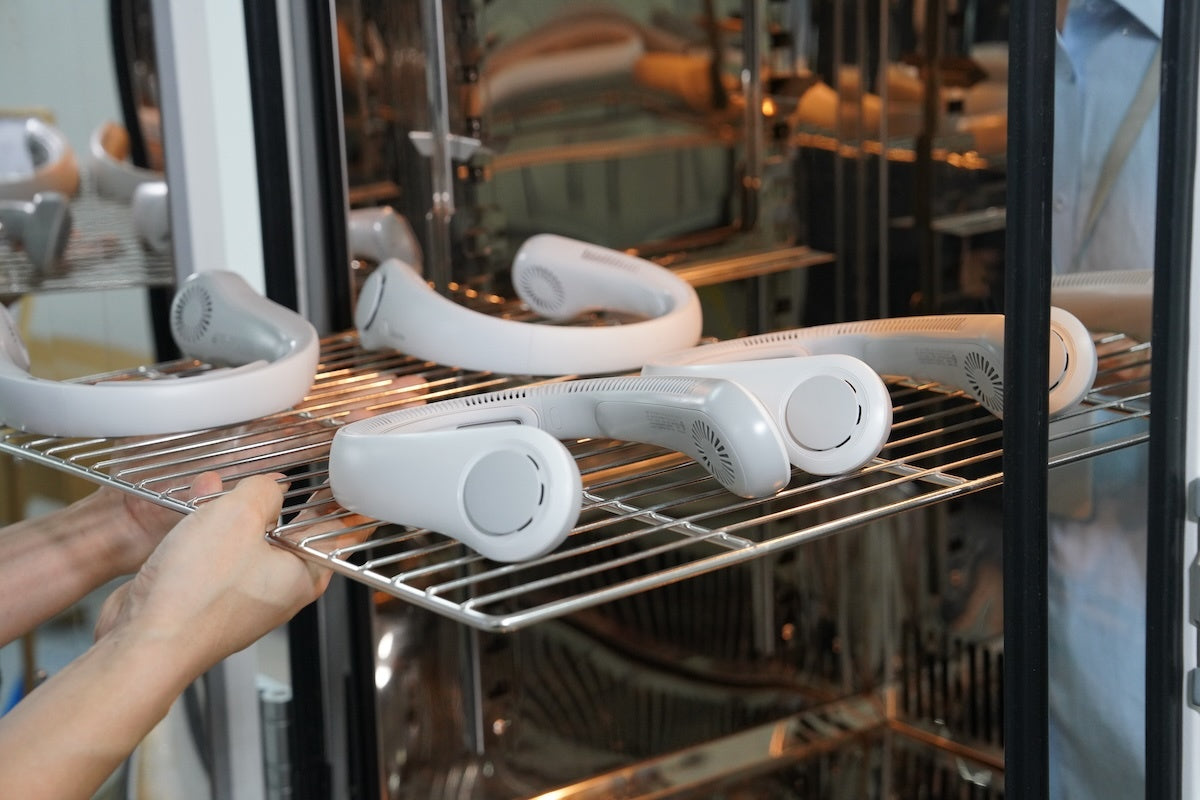
Supporting Prototyping, Validation, and Production Readiness
Getting a product ready for the market involves more than just making sure it works. It requires a rigorous process of testing and validation to ensure it can be built reliably.
Collaborative Prototyping and Validation
Prototyping is not just about making a single version of the product: it is about testing the manufacturing process itself. Instead of going straight from a design freeze to the final tooling, collaborative prototyping involves multiple build stages. The first build stages are usually dedicated to finding out about the fit, usability, and basic functionality of the parts.
By using cross-functional insights, the team can use the prototyping phase to validate the assembly instructions and the testing fixtures. This means that by the time the project reaches mass production, the factory already knows exactly how to build it. There are no surprises and no trial and error on the factory floor. Using prototypes to validate the design to manufacturing workflow provides the data needed to make final adjustments with confidence.
Achieving Production Stability
Production stability means that the thousandth unit off the line is just as good as the first one. This is achieved by having a clear set of standards and a stable manufacturing process. Following ISO standards for product testing ensures that these validations meet international quality requirements. Integrated capabilities allow for the creation of custom jigs and fixtures that hold parts in place during assembly.
Stability also comes from a deep understanding of the cycle times. If the molding process is too slow, it creates a bottleneck for the assembly team. By looking at the entire system as one unit, engineers can balance the line. They ensure that every stage of the process moves at the right speed to keep the factory running smoothly and efficiently. This prevents the "stop and start" production that ruins manufacturing profitability.
Improving Assembly Efficiency and Production Stability Through Integrated Capabilities
The final assembly line is where the true cost of a product is determined. Even a small improvement in assembly efficiency can save a company millions of dollars over the life of a product.
The Benefits of Part Consolidation
One of the most effective ways to improve assembly efficiency is to reduce the number of parts in a product. Every screw, bracket, and cable adds time to the assembly process and creates another opportunity for a mistake. An integrated design team looks for ways to combine multiple parts into a single molded component.
| Aspect | Fragmented Design | Consolidated Design |
|---|---|---|
| Part Count | Several molded parts plus hardware. | One or two molded shells with integrated clips and seals. |
| Operations | Multiple alignment and fastening steps. | Single placement and closure step. |
| Fixtures and Tools | Several fixtures and torque tools. | Fewer, simpler fixtures. |
| Error Opportunities | Many joints and interfaces. | Fewer joints and simpler handling. |
In the consolidated design, work instructions are shorter, training is easier, and the line is more suitable for automation. Assembly time and error risk drop together. This shift in thinking turns the assembly process from a labor intensive hurdle into a streamlined operation.
Implementing Error-Proofing Techniques
Error-proofing is the practice of designing products so that they cannot be assembled incorrectly. This might mean making a connector asymmetrical so it can only be plugged in one way. Or it might mean using different colored screws for different sections of the device. These small details have a huge impact on the final quality of the product.
When a supplier has integrated capabilities, they can design these features into the tooling itself. They do not just rely on the skill of the workers: they build the quality into the physical parts. This leads to a much lower rate of defective products and a much higher level of customer satisfaction. It makes the entire production process more predictable and stable, which is the ultimate goal of any Design to Production plan.
The Value of Integrated Capabilities for OEM Projects
For companies looking to outsource their production, finding a partner with a wide range of skills is essential. This integration provides security and accountability that is impossible with a fragmented approach.
Centralized Accountability and Project Management
When one supplier handles everything from design to production, there is no "blame game." If a part does not fit, the supplier is responsible for fixing it. This centralized accountability simplifies project management for the client. Instead of managing five different vendors, they only have to talk to one person who has a bird's-eye view of the entire project.
This also leads to faster problem solving. In a traditional model, if a part fails, the manufacturer blames the designer, and the designer blames the manufacturer. In an integrated model, the team simply gets to work fixing the problem. They are all on the same side, and their goal is the same: a successful product launch. Reducing the number of touchpoints significantly lowers project risk and keeps the schedule on track.
Measuring the Gains With Key Performance Indicators
To move from good stories to solid business cases, teams need a few simple metrics. Part count per assembly shows how much complexity has been removed. Assembly cycle time reflects direct labor and throughput. First pass yield shows how often units go through the line without rework. Time to stable production indicates how efficiently the path gets from freeze to reliable output.
| KPI | What it shows |
|---|---|
| Part Count | Remaining complexity and consolidation potential. |
| Cycle Time | Labor content and line capacity. |
| First Pass Yield | Quality and process stability. |
| Time to Stability | Effectiveness of the design to manufacturing path. |
What to Look for in a Supplier With Integrated Capabilities
Choosing the right partner is a major business decision. Not all suppliers who claim to be "full service" actually have the in-house expertise to handle a complex project from start to finish.
In-House Engineering and Tooling Expertise
A true integrated supplier should own their own machines and employ their own engineers. Many companies act as brokers, outsourcing the work to smaller shops and marking up the price. This adds an unnecessary layer of complexity and increases the risk of communication errors. Ask to see the facility and meet the engineering team before signing a contract.
It is also important to look at their tooling capabilities. Tooling is the most difficult part of the process. If a supplier has to send their tools out to be repaired or modified, it will add weeks to your timeline. A supplier with an in-house tool shop can make adjustments in a matter of hours, keeping the project on schedule even when challenges arise.
A Proven Track Record of Success
Experience matters more than anything else in manufacturing. Look for a supplier who has successfully brought products similar to yours to market. Ask for case studies that show how they solved specific design or manufacturing challenges. A good partner will be able to explain how they improved a design to make it more efficient or how they solved a difficult assembly problem.
The culture of the company is also important. You want a partner who is proactive rather than reactive. They should be suggesting improvements to your design before you even ask for them. This collaborative spirit is what separates a simple vendor from a true strategic partner. Evaluating case studies can give you insight into how a potential partner handles real-world problems and manages the pressure of a looming launch date.
Build Your Success on a Foundation of Integrated Engineering
The most reliable way to launch a hardware product is to eliminate the walls between design and manufacturing. By focusing on an integrated strategy, you reduce risks, lower costs, and get your product to market faster. Do not let your great ideas get lost in the gap between the studio and the factory. Seek out a partner who understands the entire journey from design to production and has the technical skill to lead the way. A stronger and more integrated path is the key to a reliable and successful product launch.
About WEILAN: Your Integrated Partner for Production Success
Finding a supplier that truly understands the journey from a digital concept to a finished product is the key to a successful launch. WEILAN provides a comprehensive suite of plastic manufacturing solutions designed to bridge the gap between design and reality.
As a specialist in plastic injection molding, WEILAN offers more than just part production. Our team provides in-house engineering support, precision tooling, and high-volume assembly services all under one roof. By focusing on a Design to Production philosophy, WEILAN helps OEMs identify potential issues early through detailed DFM and DFA reviews, ensuring that every project is optimized for speed, reliability, and cost-efficiency.
Whether you are scaling a complex new invention or looking to improve the stability of an existing product line, WEILAN acts as a strategic partner. Our commitment to integrated engineering means fewer change orders, faster ramp-ups, and a more reliable path to market for high-value hardware projects.

Leave a comment
All comments are moderated before being published.
This site is protected by hCaptcha and the hCaptcha Privacy Policy and Terms of Service apply.